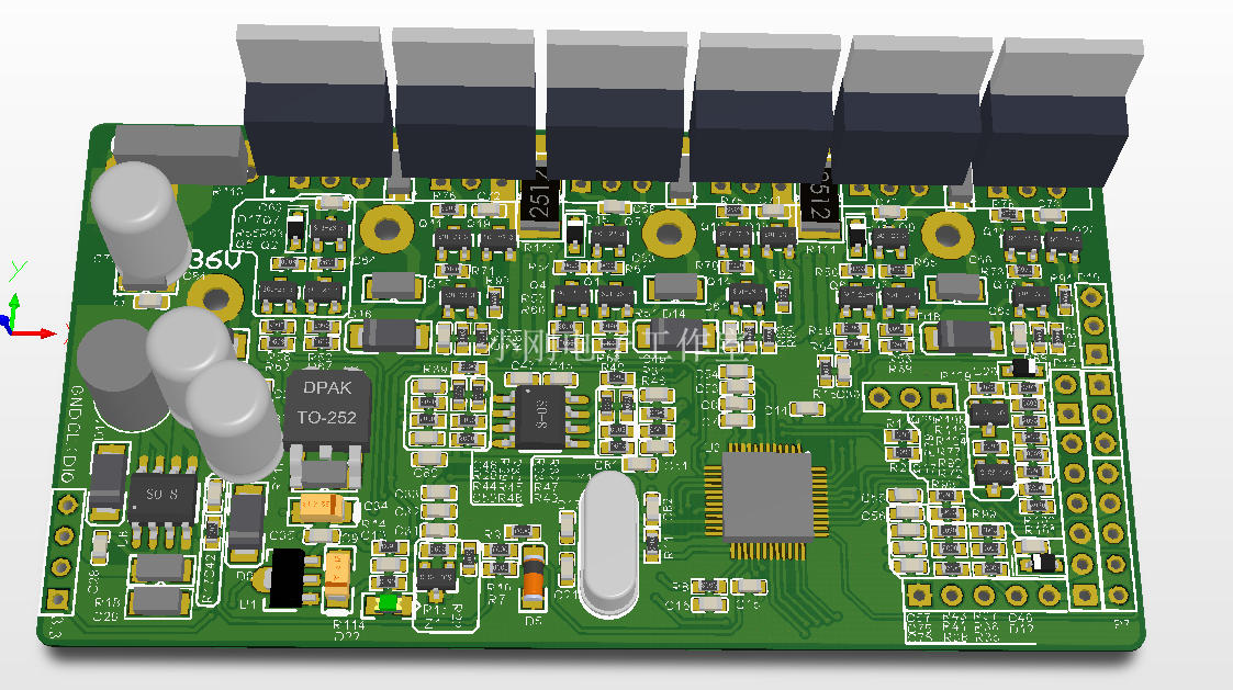
Validation checks are in place at the time of component saving, to ensure compliance.Ī component template is also a basis for creation of a generic component. Through the template, you can control which of those parameters are to be made visible, fill-in default values, and even mark those parameters that are required as mandatory. In particular, component templates have been developed with parametric information firmly in mind, allowing you to define, in a single location, a 'bucket set' of parameters that will be made available to the referencing component. Just as a schematic template can be used to predefine information on schematic sheets that reference it, a component template is referenced by a Workspace library component and provides predefined settings for use when defining that component. Helping to streamline the creation of your components, Altium Designer, in conjunction with your connected Workspace, supports creating and defining Component Templates (Component Template Items) in that Workspace. As such, this functionality will not be available with this level of access to Altium 365. Symbols/Passives/SCH - PASSIVES - CAPACITOR.When connected to an Altium 365 Workspace, note that Component Templates are not supported with the Altium Designer Standard Subscription. Table 106 Capacitors - SMD Ī descritption make the usage of the component easier to the designerįootprints/Capacitor - Chip/PCB - CAPACITOR - CHIP - CAPC_0603.PCBLIB The table cells, which are here described in detail is from “Capacitors - SMD” table as an example. Press OK and fill out the missing cell (in this example, “ComponentLink1Description”). See Symbols and Footprints on how to extract the symbol from different sources. The schematic symbols are located under alitum_libraries\symbols If the schematic does not exist, copy the schematic symbol in the suitable directory under alitum_libraries\symbols. In case of doubt the symbol and the footprint supplied by the manufacturer must be used instead of using an existing footprint.Ĭheck if the schematic symbol already exists as a symbol in the Bitbucket system. The mapping of the pins is done with the pin numbering (pin 1 of the symbol is mapped to pin 1 of the footprint and so on).


The number of pins on the symbol must match the number of pins on the footprints. Only if the component has a different geometry or pinout, a new schematic and/or footprint must be added. This means that schematics and footprints symbols of generic components only have to be in the Bitbucket repository once, even if there are multiple physical components available (e.g. The goal of this database system is that schematic and footprints of generic components only exist once.


 0 kommentar(er)
